

Screw disassembly, installation, production, regular inspection, shutdown and storage of detailed steps
Published on:
2023-08-07
Screw disassembly and installation is the customer has been very concerned about the problem, here to teach you how to correctly and effectively replace and install the screw.

1.The induction of the screw and the installation is the customer has been concerned about the problem, here to teach you how to correctly replace and install the screw.
2.(Figure) Detailed steps of mouse sensing and installation (1)
3. Screw induction steps and production and common precautions:
3.1 The temperature of the material tube should be increased by an appropriate temperature (10℃ to 20℃ higher than the usual production temperature). (Depending on the temperature required to produce the material at each time), this step can be used when the equipment is ordered, repaired or changed each time.
3.2 Add the cleaning pipe material (such as PP material), and then empty all the material in the pipe (including PP material). This step can be used when the equipment is frequently ordered, repaired or changed.
3.3 Screw loose to the end.
3.4 Adjust the mold opening position and mold thickness position to the maximum (the mold on the machine needs to be removed).
3.5 Remove the upper cover of the ejector seat and the ejector shield.
3.6 Turn off the main power supply.
3.7 Remove the heating ring and temperature sensing wire on the nozzle and flange.
3.8 Remove the screw tail screw with a hex wrench to separate the screw from the motor (Figure 1, Figure 2).
3.9
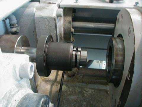
Figure 1 Tightening the fixed screws
3.10
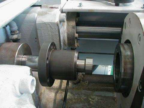
FIG. 2 Screw is separated from motor
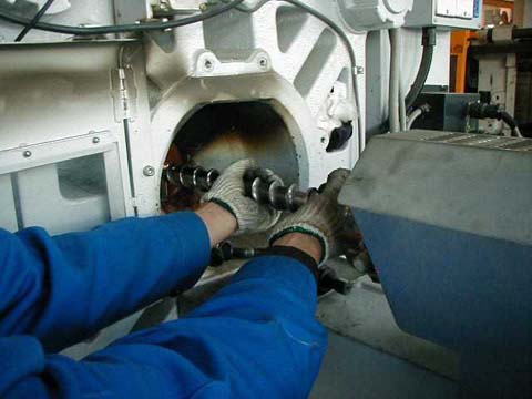
3.11 Hold the two clasp rings at the end of the screw and put forward the flange (Figure 3, Figure 4, Figure 5).
3.12
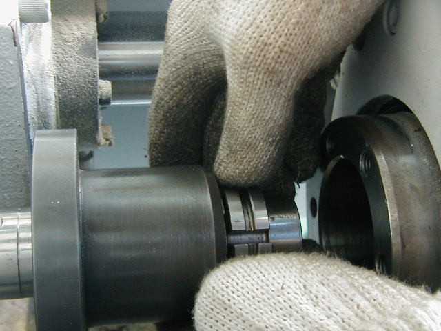
Figure 3 Removing two clasp rings
3.13
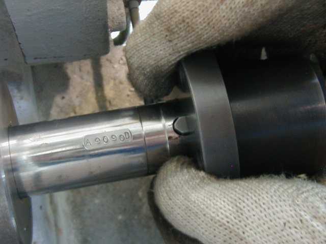
4 Removing flange
3.14

Figure 5 Flange behind
3.15 Remove the screws and flanges of the screws and remove them. (Figure 6, Figure 7, Figure 8)
3.16
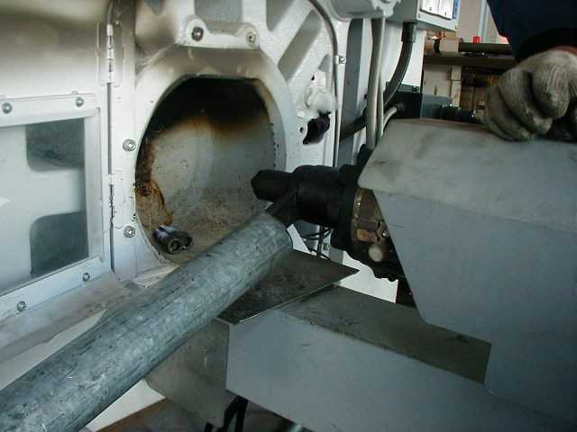
Figure 6 Removing the nozzle
3.17 (Figure) Screw sensor, detailed steps of installation (2)
3.18
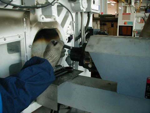
Figure 7 Tightening the screws of the lower flange
3.19
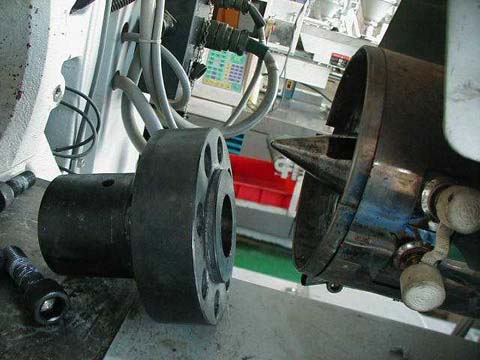
Figure 8. Craned flange
3.20
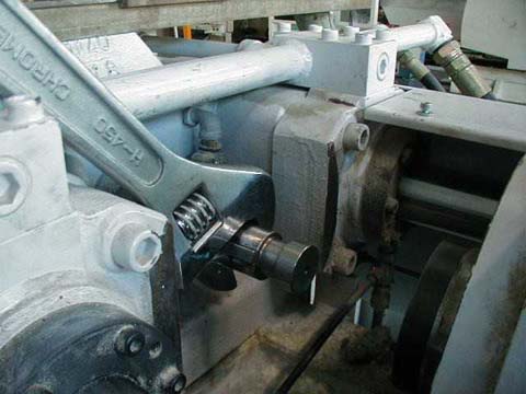
Figure 9 Pull the screw tail
3.21
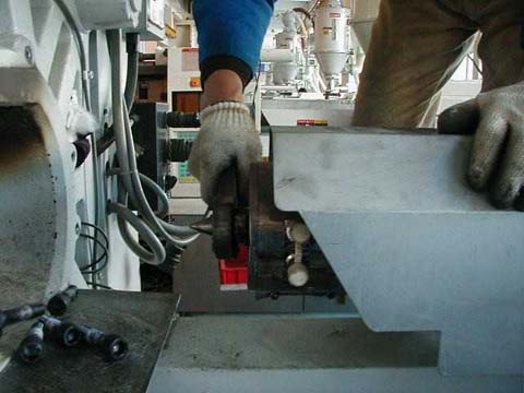
Figure 10 Pull off the screw head
3.22
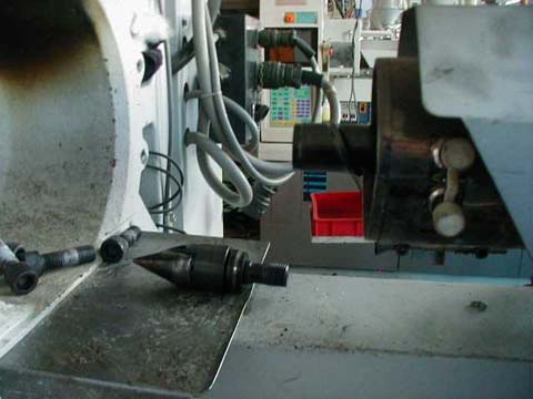
Figure 11 Carry screw head group
3.23
3.24 Figure) Detailed steps of screw induction and installation (3)
3.25 Detailed steps of screw installation:
3.25.1 Install the upper flange, and the front end of the screw that fixes the flange should be covered with anti-heat oil, and should be tightened diagonally (as shown in FIG.1 and FIG.2, the same person should complete the installation to ensure that the force and diagonally are not damaged during locking).
3.25.2
Figure 1 Coated with COPPER COMPOUND (SPANJAARD, UK, temperature resistant to 890°C)
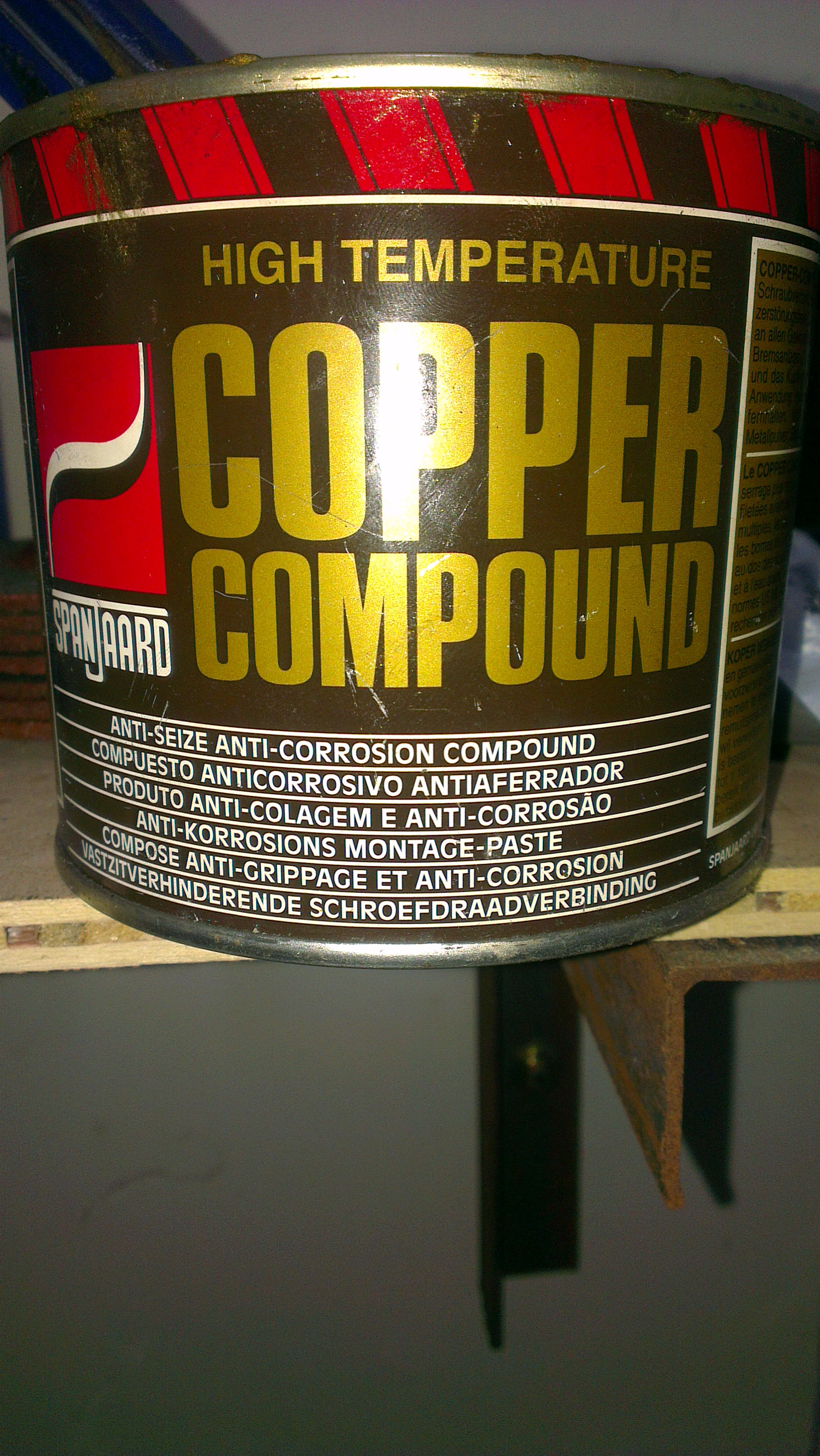
Anti-corrosion paste
3.25.3
Figure 2 Diagonal tight flange screws
3.25.4 Install the heating ring, temperature sensing wire and injection shield on the nozzle flange.
3.25.5 Install the upper key at the end of the screw, connect the two clasp rings of the flange with the motor, and cover the shooting seat cover.
(Figure 3, Figure 4, Figure 5, Figure 6)
3.25.6
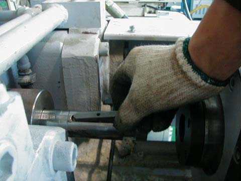
Figure 3 Installing the upper key
3.25.7
3.25.8
Figure 4 Fitting the flange
Figure 5 Install two semicircles
3.25.9
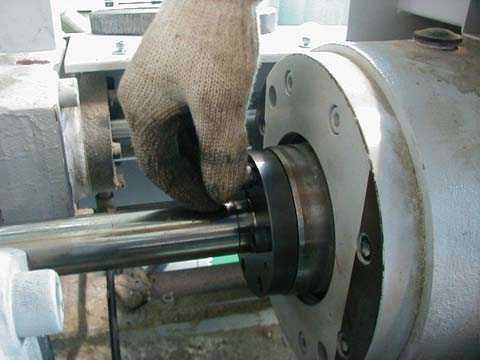
Figure 6 Screw on
4 Machine finishing
5 Store:
5.1 Evenly apply a layer of anti-rust oil (10W-40, if not used for more time, butter is recommended) to the whole set of material tubes (including tube wall, screw tube, flange, nozzle, glue (rocket) head, rubber ring and glue meson). 5.2
Then it is covered with a telescopic film.
5.3 Name and specifications of the equipment to be used (e.g. Diameter...) .
5.4 The whole group of material pipes shall be placed flat on the shelf as shown in the figure.
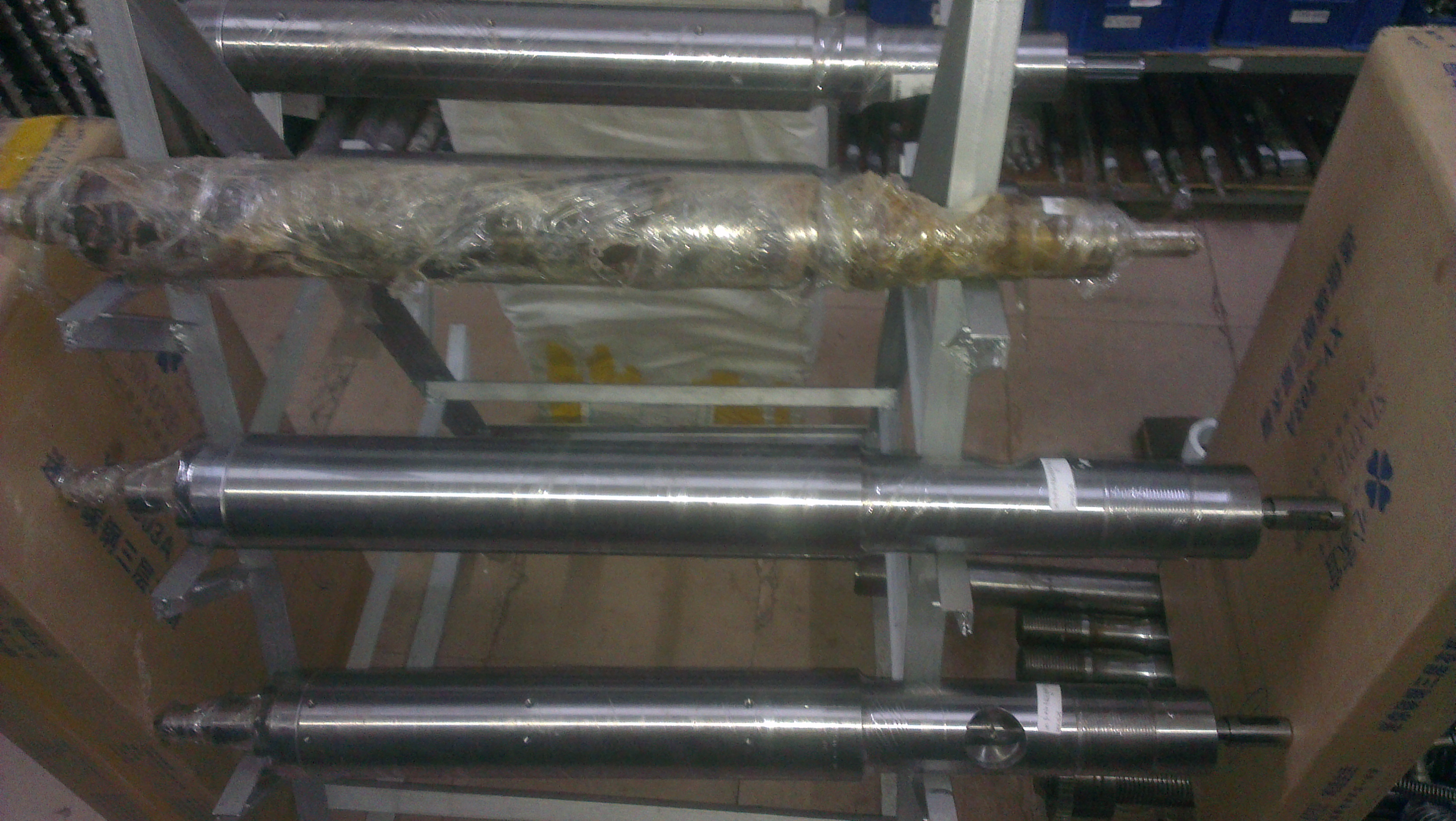
The screw is stored in the way of suspension to prevent flat deformation and bending.

In addition, the storage nozzle, rubber (rocket) head, rubber ring, rubber meson with plastic support box, chassis fall damage.

Adjust nozzle center:
For example: VE series sometimes remove the material tube, will move out of the ejector seat, and then lift the discharge tube, at this time the center of the nozzle will be offset, need to be adjusted.
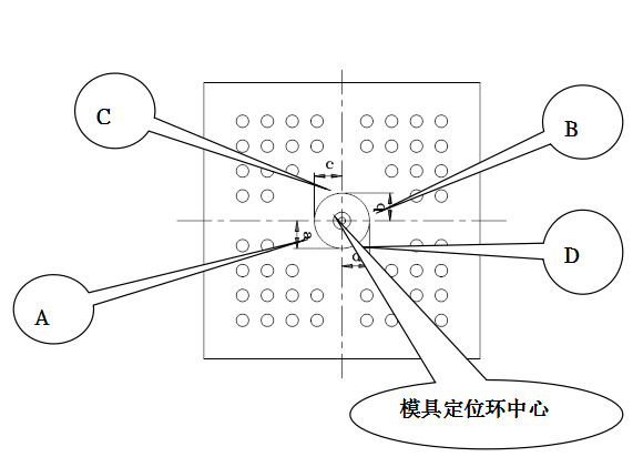
Lock the ejector link fastener.
Loosen the seat mechanism adjustment screw.
The seat advances to the center point of the inner plane of the nozzle and the head plate.
Measure the distance between the nozzle and the mold fixing ring on the head plate, and adjust the screw of the seat structure to achieve the symmetry between the distance and the fixing ring (the error from point A, B, C, D to the center shall not exceed 0.05mm).
Lock the seat mechanism adjustment screw to ensure that the distance is no longer offset.
7 After the installation of the tube screw, the following points for startup debugging:
7.1 For the first heating, set the temperature to 180∘C, maintain the temperature for 5 minutes after reaching the temperature, and then set the required temperature (such as 250∘C), after reaching the required temperature, continue heating for 15 minutes before starting.
7.2 Slowly test the ejection and release action manually for 5 times (do not add plastic at this time, pay attention to the ejection position should be "0"), and then test the feeding action without friction noise.
7.3 Forward the seat to the end (towards the mold direction), check whether the heating wire is properly finished.
8 Material tube screw regular inspection method:
8.1 Reasons and methods for determining whether the material tube screw can continue to be used or scrapped:
8.1.1 Reasons: For different molding products, due to the quality accuracy requirements of different products, our company can provide regular inspection data, but can not determine whether the wear part can continue to use or scrap.
8.1.2 Mode: Continue to use or scrap? After all, it is necessary to return the result of product quality judgment after customer molding.
8.1.3 Replacement: For products with high precision, the material screw is no longer suitable, and the product with low precision can be converted.
8.2 Regular inspection:
8.2.1 Specifications of newly fabricated pipe screw, providing design tolerances of key dimensions.
8.2.2 After the warranty period, polishing and testing of PA46 halogen-free pipe will be carried out every three months, each time taking 3 working days (including disassembly), and the measured data will be provided for customers' reference!
8.2.3 After the warranty period, the LCP material pipe shall be polished and tested every six months, each time taking 3 working days (including disassembly), and the measured data shall be provided for customers' reference!
8.2.4 The customer obtains the measurement data, and then combines with its own product characteristics after forming, to determine whether the original product should continue to be produced, the product should be replaced or the material tube screw should be scrapped.
Previous page
Related News
Related News

Follow us
Phone:86-769-81661345
Address: No. 63, Shuan Road, Humen Town, Dongguan City, Guangdong Province
Copyright © 2023 Dongguan Xingyou Machinery Equipment Co., Ltd
Prowered by 300.cn SEO Business license


